
 EN
EN
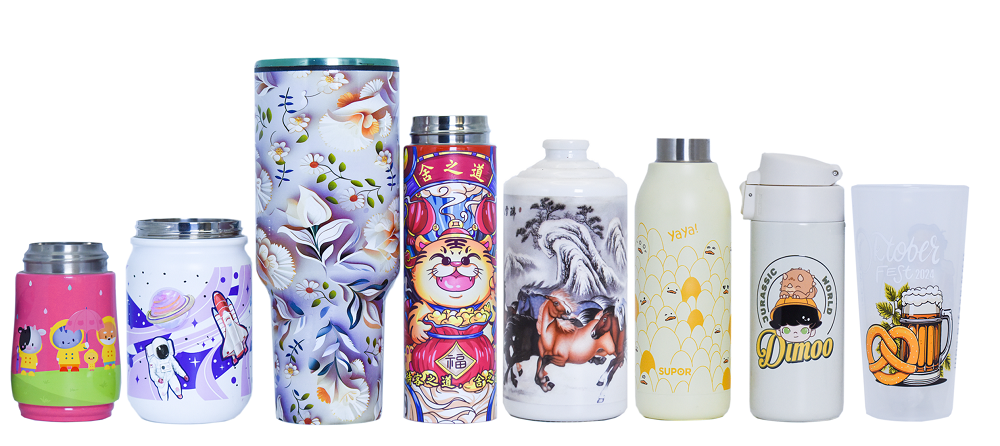
The Challenge That Tapered Shapes Present
Printing on a straight cylinder is relatively straightforward. The surface moves past the printhead at a consistent distance, and the geometry doesn't change from top to bottom. A tapered cylinder—wider at one end, narrower at the other—breaks that simplicity. The distance between the printhead and the surface varies along the length of the object, which affects droplet placement and image fidelity.
This isn't a niche problem. Tapered containers appear across beverage packaging, cosmetic jars, promotional drinkware, and industrial components. Any cylindrical object with a draft angle—the slight taper that helps with molding or stacking—presents the same fundamental challenge. The inkjet industry has responded with a range of technical approaches, each with its own tradeoffs.
Understanding the Geometry of Taper
Before solving the printing problem, it helps to understand what's actually happening on a tapered surface. A straight cylinder has a constant radius. When it rotates, every point on the surface moves at the same linear speed relative to the printhead. A tapered cylinder has a radius that changes along its axis. The wider end travels a longer circumference per revolution than the narrower end. If the rotation speed is constant, the surface speed at the wide end is higher than at the narrow end.
This speed differential creates two problems. First, the ink droplets land at different intervals along the length—compressed at the narrow end, stretched at the wide end—unless the firing timing compensates. Second, the varying distance from printhead to surface affects droplet size and placement accuracy. Printheads are designed to fire at a specific working distance; deviation from that distance changes the dot size and can cause misregistration.
One equipment manufacturer's engineering team described the challenge this way: printing on a tapered cylinder is like trying to paint a straight line on a cone while it spins—the line will naturally curve unless the application system actively corrects for the changing geometry.
Variable Speed Control: The Foundation of Taper Printing
The most common approach to tapered cylinder printing involves variable speed control during the rotation cycle. Instead of rotating the cylinder at a constant angular velocity, the drive system adjusts the speed so that the surface linear velocity remains constant across the entire printed area.
Here's how it works in practice: the printer's software calculates the radius at each point along the cylinder's length. As the printhead moves from the narrow end to the wide end, the rotation speed decreases slightly to maintain a consistent surface speed. This ensures that the inkjet firing frequency—which is timed to the surface movement—produces evenly spaced dots regardless of the local diameter.
This method requires precise feedback from the drive system. Servo motors with high-resolution encoders provide the positional data needed to make these adjustments in real time. The printhead firing is synchronized with the rotation, so each droplet lands exactly where the digital file specifies, accounting for the changing surface speed.
Some cylinder inkjet printers incorporate this capability as a standard feature, with software that automatically maps the taper profile before printing begins. The operator enters the diameters at both ends and the length, and the system generates the compensation curve.
Printhead Positioning and Throw Distance
Surface speed isn't the only variable. The distance from the printhead to the surface—the throw distance—changes along a tapered cylinder if the printhead remains in a fixed position. A printhead designed for a 2mm working distance will produce acceptable results within a certain tolerance band. Beyond that, dot gain and loss of sharpness become noticeable.
Some systems address this by keeping the printhead at a fixed distance and designing the inkjet system with a wider depth of field—the range over which acceptable print quality is maintained. This approach relies on printhead technology that can produce consistent droplets across a range of distances, typically through higher drop velocities and tighter drop formation control.
Other systems physically adjust the printhead position during printing, moving it closer or farther to maintain a constant working distance. This adds mechanical complexity and requires precise coordination between the printhead positioning axis and the rotation axis. The tradeoff is better image quality on extreme tapers where the diameter changes significantly over a short length.
Industry examples show that systems capable of handling tapered vessels with diameter variations of 15mm or more are becoming available. The practical limit depends on the specific printhead technology and the acceptable quality threshold for the application.
Software Compensation and Image Distortion
Even with variable speed control and optimized throw distance, there's a third factor: image distortion. A rectangular image designed for a flat surface will appear distorted when wrapped around a tapered cylinder unless the software pre-distorts it to compensate.
This is where the printing software becomes critical. The raster image processor (RIP) must apply a nonlinear scaling to the image data. The narrow end of the cylinder receives more image content per unit of surface area than the wide end—the software needs to stretch the image appropriately so that when it's printed, the visual proportions look correct.
Advanced cylinder inkjet printers include RIP software with dedicated taper compensation modules. These tools allow operators to define the taper profile and preview the compensated image before printing. Some systems even use an ink droplet compensation algorithm that adjusts droplet placement to avoid deformation on different sections of the tapered object.
The compensation isn't just about stretching. Color density can also vary along the taper if the ink laydown changes with surface speed. The software may adjust the firing pattern to maintain consistent ink coverage, ensuring that the color doesn't appear lighter at one end than the other.
Practical Workflow for Tapered Cylinder Printing
For a shop setting up to print tapered cylinders, the workflow typically follows a sequence:
Measure the taper. Accurate measurement of the diameters at both ends and the overall length is essential. Some systems include automatic measurement using laser or contact sensors.
Configure the print profile. The operator enters the taper data into the printer's software, which generates the speed compensation curve and throw distance adjustments.
Prepare the image. The design file is imported into the RIP software, where the taper compensation is applied. The operator reviews the preview to confirm that the image proportions look correct.
Set up the fixture. Tapered objects require fixturing that holds them securely during rotation. Centers or chucks that accommodate the varying diameter are common.
Run a test print. A test piece—often a sacrificial sample—confirms that the compensation settings produce acceptable quality. Adjustments to the taper profile or print parameters are made as needed.
Production run. Once the settings are validated, production can proceed. The printer applies the same compensation to every piece in the run.
One facility that prints tapered promotional cups reported that the initial setup for a new taper profile took around 15 minutes. Once saved, that profile could be recalled instantly for future runs of the same product. The learning curve was less about the technology and more about understanding which taper geometries produced the best results with their specific printhead configuration.
Limitations and Realistic Expectations
Not every taper is printable with every cylinder inkjet printer. The maximum taper angle that a system can handle depends on the printhead's depth of field, the available throw distance, and the software's compensation capabilities. Extreme tapers—where the diameter changes by more than 30% over the length—may require specialized equipment or alternative printing methods.
There's also a practical limit on print resolution at the extreme ends of the taper. Even with compensation, the narrow end has less surface area per unit length, which can limit the amount of detail that can be reproduced. High-density graphics may need to be simplified or scaled appropriately.
Surface condition matters too. Tapered cylinders that are out-of-round or have significant surface irregularities will compound the printing challenges. Good fixturing and a consistent substrate are prerequisites for acceptable results.
A manufacturer of tapered packaging containers found that their cylinder inkjet printer produced excellent results on tapers up to about 10 degrees included angle. Beyond that, they switched to a pad printing process for the extreme taper sections and used inkjet for the main body. This hybrid approach is not uncommon in production environments where extreme geometries are the exception rather than the rule.
Making Tapered Printing Work in Production
Printing on tapered cylinders is technically demanding, but the solutions are well understood and increasingly accessible. Variable speed control, printhead positioning, and software compensation work together to produce images that appear correctly proportioned and sharply defined across the entire tapered surface.
The key is matching the equipment capability to the specific taper geometry. A cylinder inkjet printer with robust taper compensation features can handle a wide range of tapered objects, from beverage cans with slight draft angles to cosmetic jars with more pronounced tapers. As with any specialized printing application, the results improve with experience—each taper profile teaches the operator something about the limits and possibilities of the system.
NOVA Inkjet Technology offers cylinder inkjet printers designed with adjustable tooling fixtures and flexible printing mechanisms that accommodate a broad range of cylindrical sizes and shapes. Their systems integrate the speed control and software compensation needed for consistent results on tapered substrates, reflecting a practical understanding of what production environments actually require.
Table of Contents
- The Challenge That Tapered Shapes Present
- Understanding the Geometry of Taper
- Variable Speed Control: The Foundation of Taper Printing
- Printhead Positioning and Throw Distance
- Software Compensation and Image Distortion
- Practical Workflow for Tapered Cylinder Printing
- Limitations and Realistic Expectations
- Making Tapered Printing Work in Production