
How Visual Positioning UV Inkjet Printers Eliminate Misregistration on Curved and Textured Substrates
The Core Challenge: Why Traditional UV Flatbed Printers Fail on Asymmetric Geometry
Standard UV flatbed printers work with fixed coordinates and need mechanical leveling, which makes them pretty much useless when dealing with surfaces that aren't flat or have complicated curves. The problem comes down to those rigid print paths causing ink drops to hit different spots on textured materials. On rough surfaces with lots of peaks and valleys, this leads to all sorts of issues like blurry lines, colors running together, and misalignment problems that can be as bad as 300 microns on things like curved car parts or electronic housings. There are basically three main reasons why these printers struggle so much with non-flat surfaces:
- Inability to detect surface variations in real time
- Static Z-axis calibration that ignores local height deviations
- No compensation for material warping during UV curing
Technical Foundation: Real-Time Camera-Based Feature Detection and Dynamic Coordinate Transformation
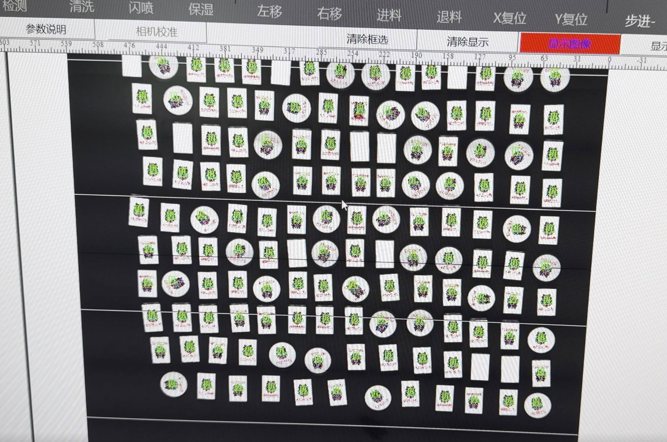
Visual positioning UV inkjet printers overcome these constraints through integrated machine vision and closed-loop motion control. High-resolution cameras scan the substrate before printing, identifying fiducial markers and mapping surface contours via laser triangulation—generating a precise 3D topographic map within milliseconds. This data drives dynamic, real-time adjustments to:
- Printhead trajectory, using servo-motors to maintain consistent nozzle-to-surface distance across Z-axis deviations
- Droplet timing, synchronized to instantaneous surface distance for optimal placement
- Ink delivery parameters, adapting viscosity and drop volume for porous and nonporous zones
The system transforms coordinates continuously in sync with conveyor movement, achieving <20 µm registration accuracy. Industry validation shows a 98% reduction in rework versus traditional methods—enabling reliable, high-fidelity decoration of medical devices, ergonomic tools, and other complex geometries previously considered unprintable.
From Manual Leveling to Smart Profiling: How 3D Scanning + Fiducial Recognition Enables One-Touch Setup
Trying to level things manually just doesn't work well when dealing with warped surfaces or textured materials. It takes forever to get right through all those trial and error adjustments, which really slows down production lines. That's where modern visual positioning systems come into play. These systems profile substrates automatically using laser triangulation scanners that map out surface details at around 20 thousand points per second. At the same time, machine vision tech spots those registration marks with incredible accuracy down to under 20 microns. What happens next is pretty cool actually. The system builds a digital copy of every single part, figuring out exactly where the print heads need to go without any human input required. Factories have seen amazing results from this approach. One touch setup cuts calibration time nearly three quarters in real world tests. And guess what? First pass failures almost disappear completely, even when printing on tricky stuff like curved car interiors or weird wood grain patterns. Less wasted material means happier bottom lines for manufacturers.
Closed-Loop Real-Time Compensation: Synchronizing Vision, Motion, and Inkjet Timing
Getting sub-20 micrometer accuracy on those complicated 3D surfaces requires all systems to work together perfectly. The visual positioning UV inkjet printers do this magic via something called closed loop real time compensation. Basically, these high speed cameras keep sending position updates to the motion controllers non stop. Then the controllers make adjustments to both the robot's movement and when the ink gets ejected. This whole process cancels out errors that build up over time because of things like heat changes, vibrations in the system, and how materials stretch and contract during operation. Manufacturers need this level of precision for applications where even tiny mistakes can cause big problems down the line.
Bridging the Latency Gap: Sub-millisecond Vision Processing and Servo Feedback Integration
Legacy systems suffer from vision-to-motion delays exceeding 10 ms—causing misalignment on fast-moving lines. Modern platforms reduce latency to <1 ms using:
- FPGA-accelerated image processing for instant feature recognition
- Direct servo motor feedback integration via EtherCAT networks
- Predictive motion algorithms that anticipate substrate position based on real-time velocity and acceleration data
This enables stable, continuous compensation for conveyor speed fluctuations (±0.2 m/s) and ambient temperature shifts—without interrupting throughput.
Performance Validation: 92% Reduction in Z-axis Drift (ASTM D7529) and <±15 µm Registration Consistency
Rigorous testing per ASTM D7529 across 500+ cycles confirms robust performance under industrial conditions:
| Metric | Traditional System | Closed-Loop System | Improvement |
|---|---|---|---|
| Z-axis positional drift | 85 µm | 6.8 µm | 92% reduction |
| Registration consistency | ±42 µm | ±14.7 µm | 65% tighter tolerance |
| Thermal drift (−30°C) | 73 µm | 8.2 µm | 89% reduction |
The system maintains sub-15 µm accuracy even on surfaces with 1.5 mm height variations—and sustains it through automatic recalibration every 45 minutes during continuous operation.
Multi-Axis Coordination for True 3D Surface Printing
Standard fixed axis UV systems struggle to keep the same distance between nozzles and surfaces when dealing with complex shapes or sharp angles. This often results in registration issues along edges and reduced print quality. The solution comes from visual positioning systems paired with multi axis motion control. These setups use robotic arms that adjust printheads as needed during operation, keeping nozzle surface distances around 50 microns even when angles go beyond 45 degrees. Servo motors work at about 2 kHz, making constant adjustments possible even when moving at speeds over 1 meter per second. Research shows these systems can hit under 20 microns accuracy on complicated curved surfaces. What does this mean practically? No need for tedious manual adjustments and roughly 37% less wasted materials compared to older fixed axis methods. Manufacturers can now print three dimensionally on things like turbine blades, medical equipment casings, and specially shaped tools without losing clarity on steep slopes, deep grooves, or small radius curves.
FAQ Section
What makes visual positioning UV inkjet printers better for curved and textured surfaces?
These printers use machine vision and closed-loop motion control to dynamically adjust printhead trajectories based on real-time 3D mapping of the substrate, reducing misalignment and improving print quality on complex surfaces.
Why do traditional UV flatbed printers struggle with non-flat surfaces?
Traditional printers rely on fixed coordinates and static Z-axis calibration that do not account for surface variations, causing misregistration and quality issues on uneven surfaces.
How do visual positioning systems achieve precise alignment on complex substrates?
They integrate high-resolution cameras that scan and map the surface using laser triangulation, creating a digital topographic map that guides accurate printing adjustments in real time.
What are the benefits of using closed-loop real-time compensation?
This technology synchronizes vision, motion, and inkjet timing, minimizing errors caused by heat changes, vibrations, and material movements, essential for high-precision printing applications.
Table of Contents
-
How Visual Positioning UV Inkjet Printers Eliminate Misregistration on Curved and Textured Substrates
- The Core Challenge: Why Traditional UV Flatbed Printers Fail on Asymmetric Geometry
- Technical Foundation: Real-Time Camera-Based Feature Detection and Dynamic Coordinate Transformation
- From Manual Leveling to Smart Profiling: How 3D Scanning + Fiducial Recognition Enables One-Touch Setup
- Closed-Loop Real-Time Compensation: Synchronizing Vision, Motion, and Inkjet Timing
- Multi-Axis Coordination for True 3D Surface Printing
- FAQ Section